Van Build
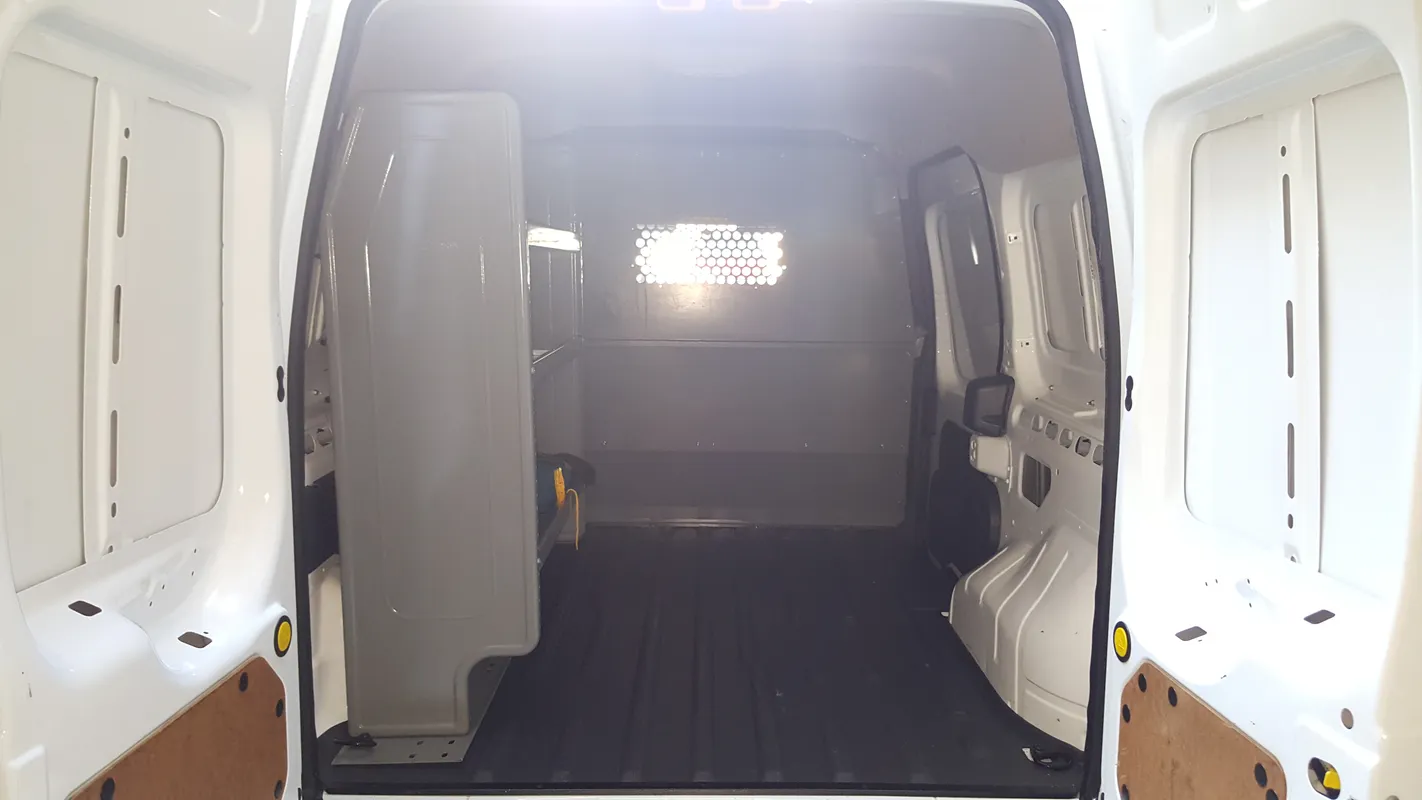
Initial Tear Down
In preparation for the conversion, the felt ceiling liner, vinyl flooring mat, utility shelving, and door paneling were stripped down
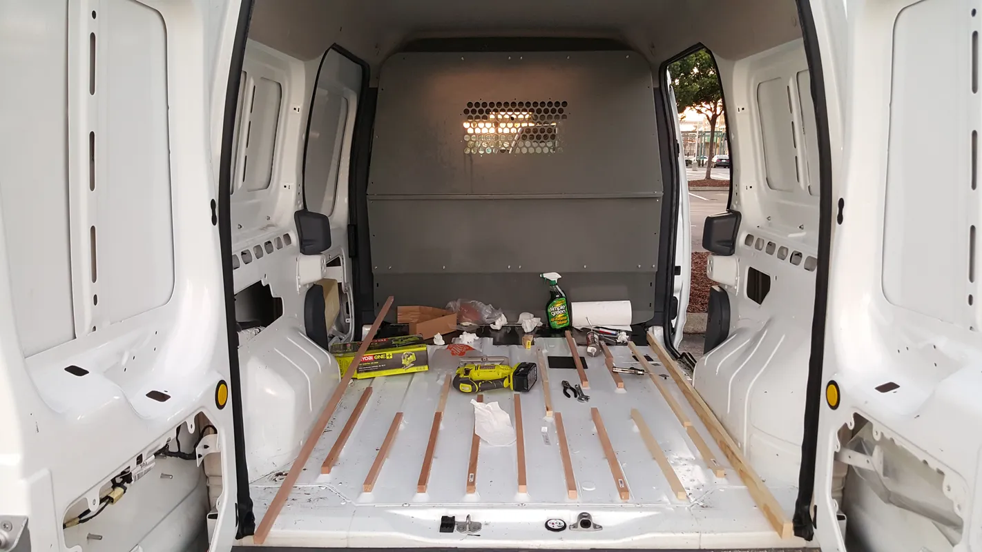
Substructure and Insulation
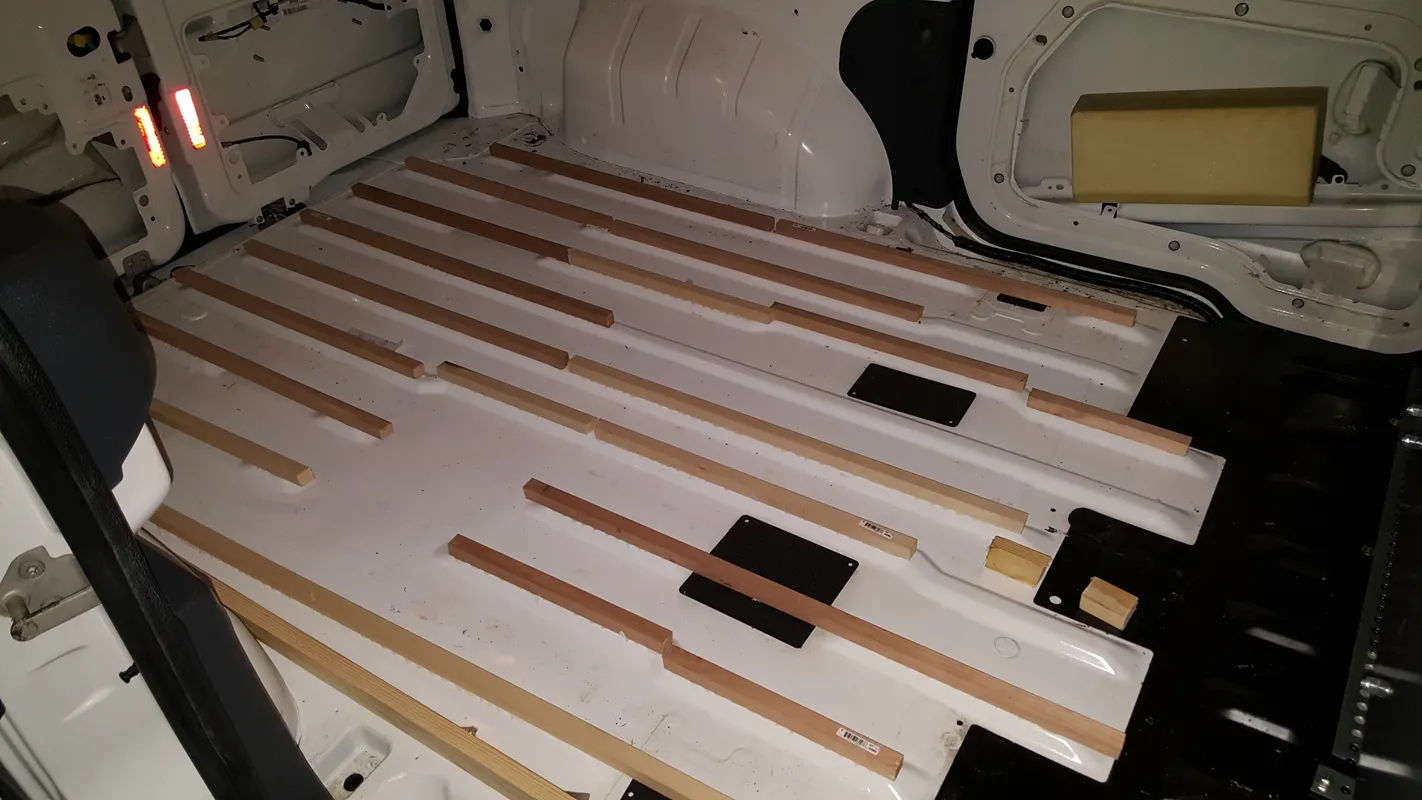
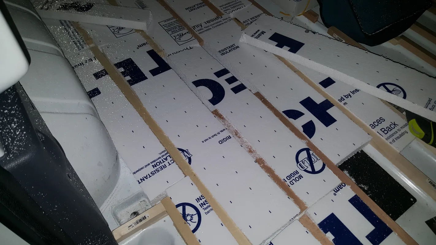
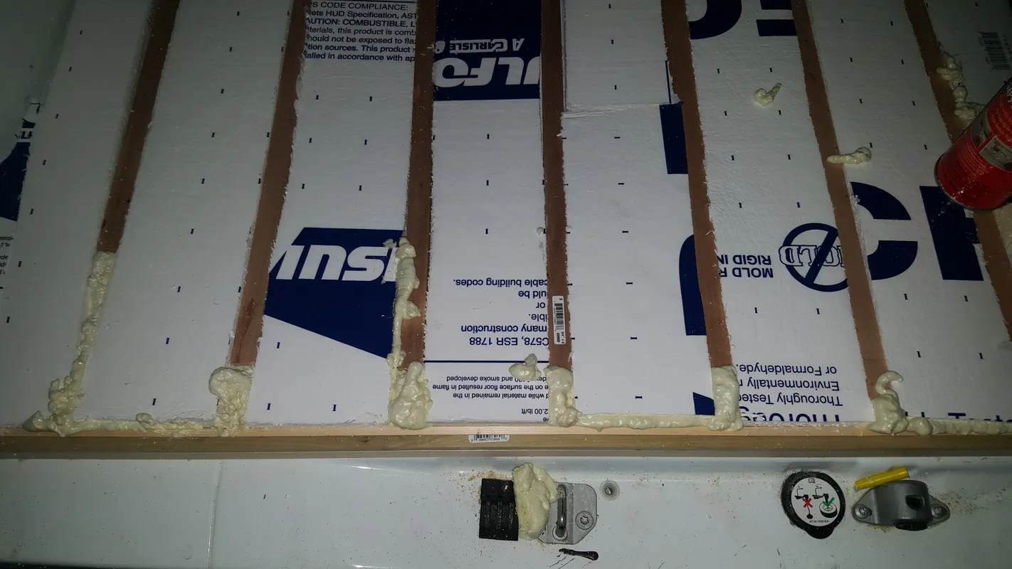
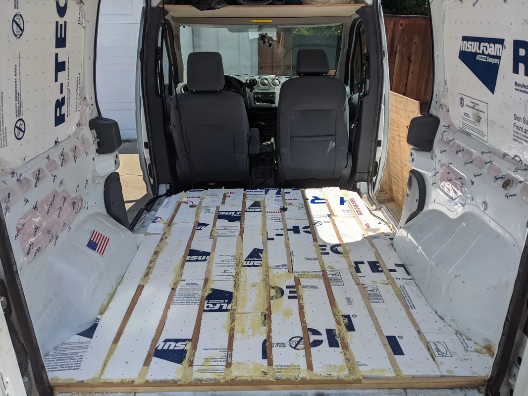
3/4” x 3/4” Wooden “beams” were epoxied down to the aluminum ridges on the van’s cargo floor as the sub structure. In between the beams is a continuous infill of rigid insulation, with spray foam insulation in the seams and gaps. The height of the metal floor ridges allowed the substructure and insulation to sit about and inch above the van’s metal floor, leaving a significant “air gap” which is a crucial element for a well insulated space. Additionally, there is a foil lining on the side of the insulation facing the floor to help deflect radiant heat.
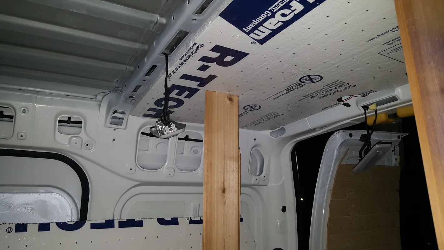
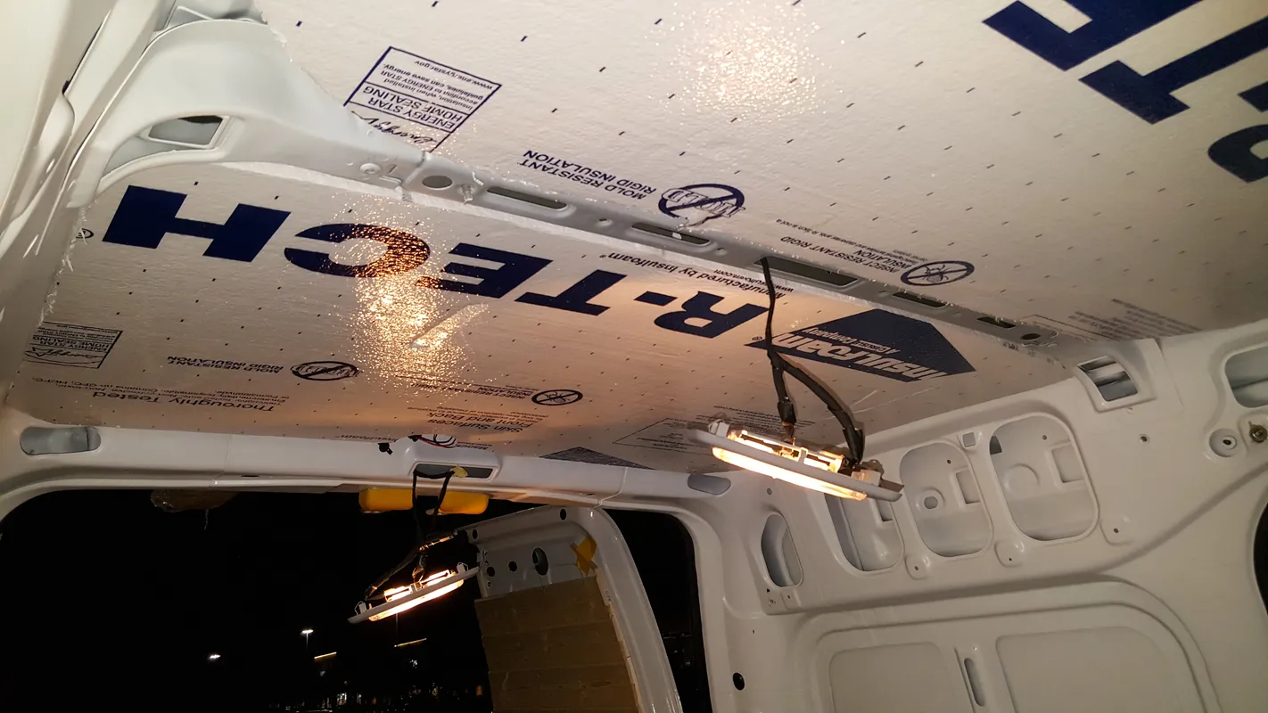
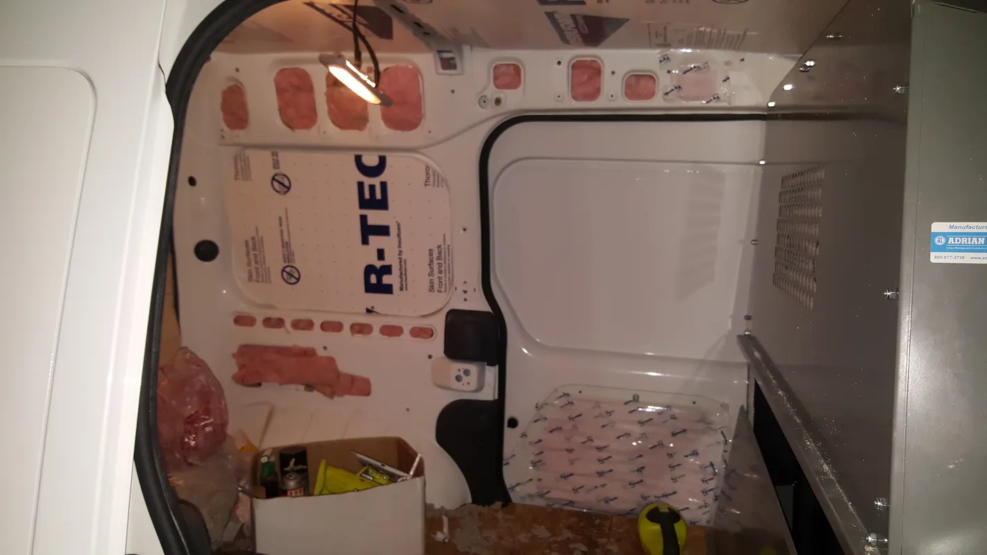
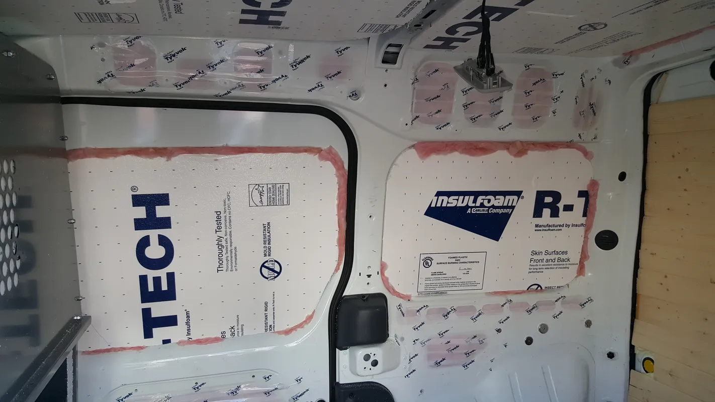
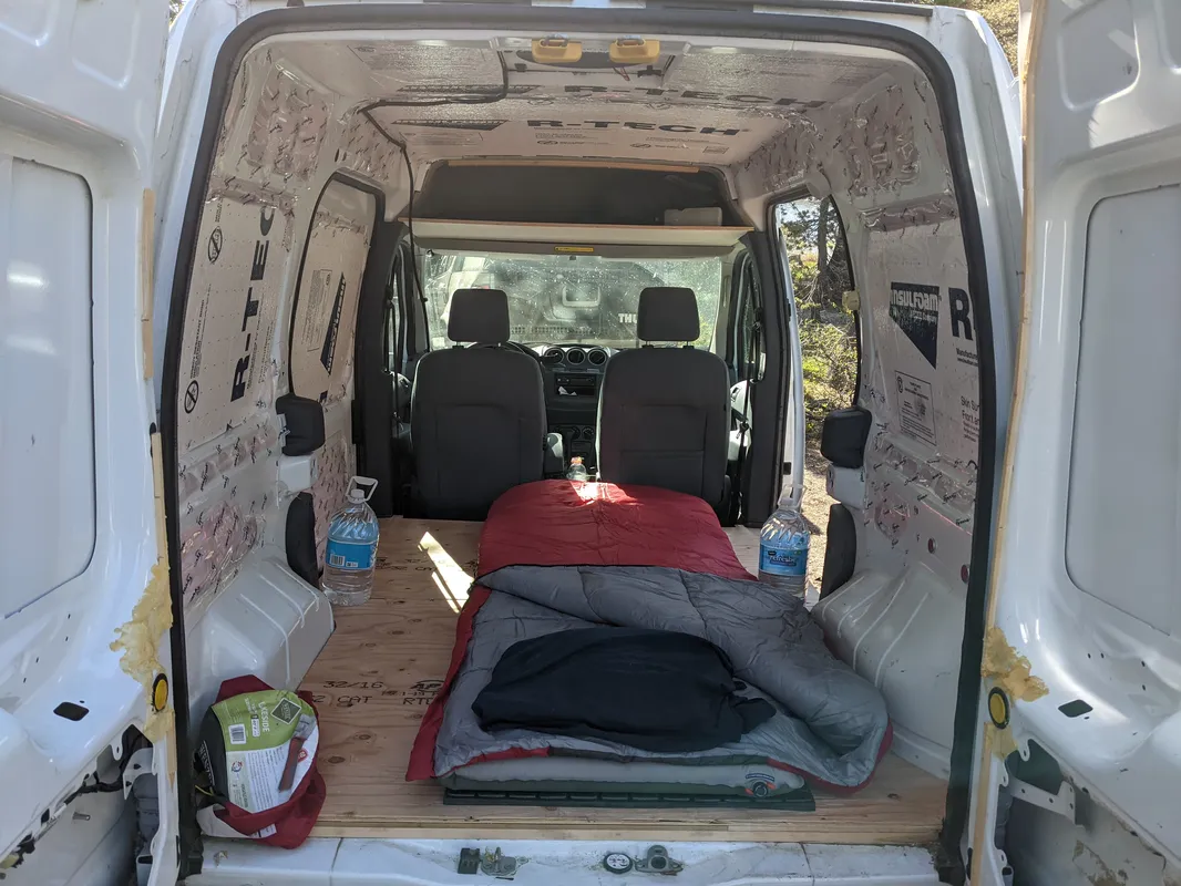
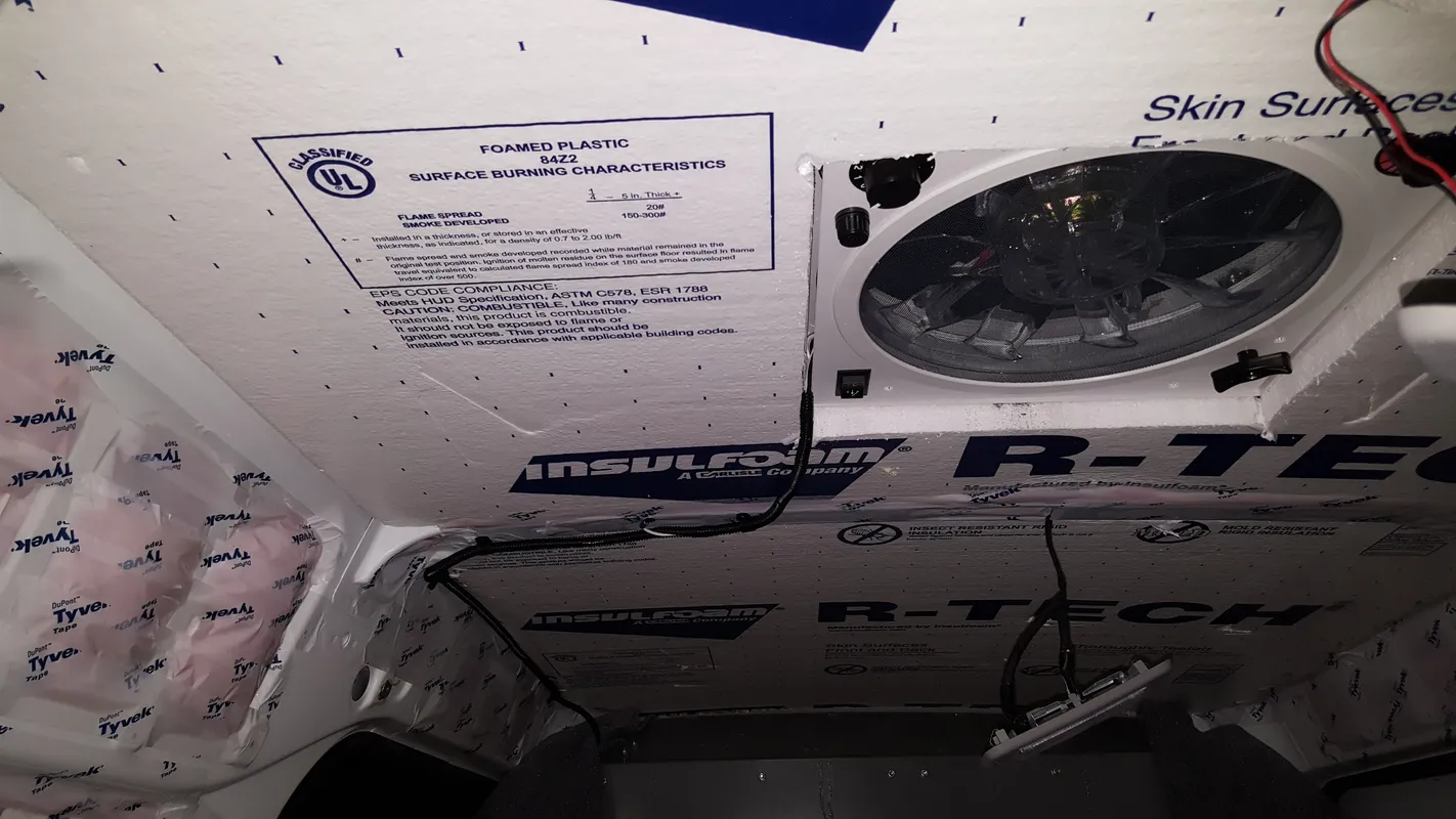
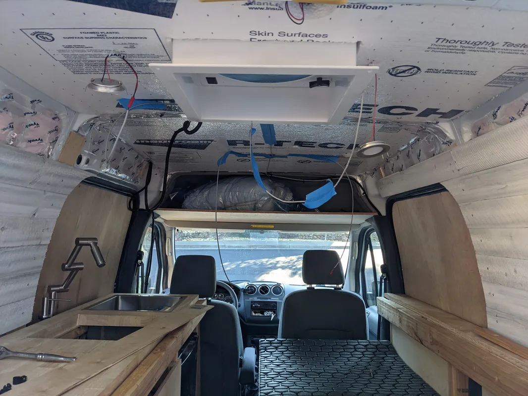
Similar to the floor, a layer of rigid foam insulation is adhered to the metal corrugated structural ridges of the chassis ceiling. By laminating the underside of these ridges, a significant air gap was left in-between the underside of the van’s metal roof and the top of the insulation layer, maximizing the performance of the insulation layer. Additionally, the rigid foam has a thin layer of reflective foil on its top side, which helps mitigate the high amount of radiant heat coming from the sun on the roof.
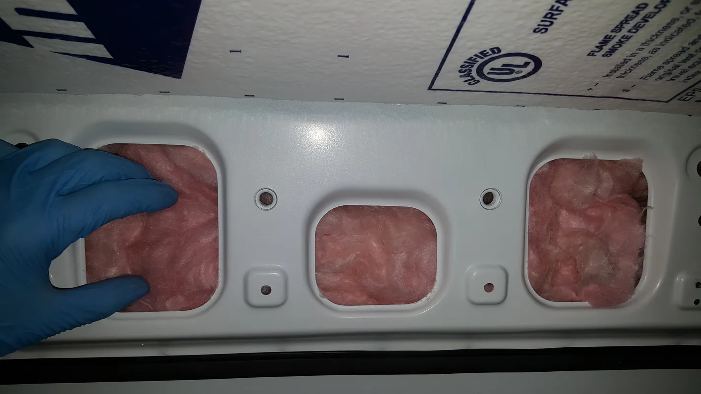
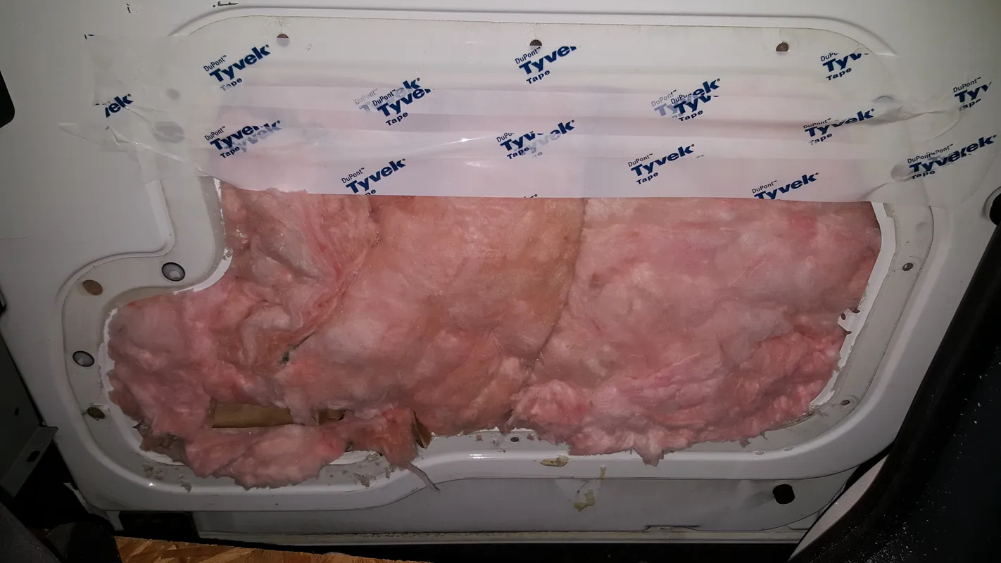
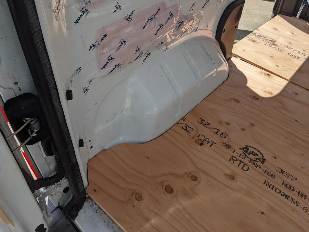
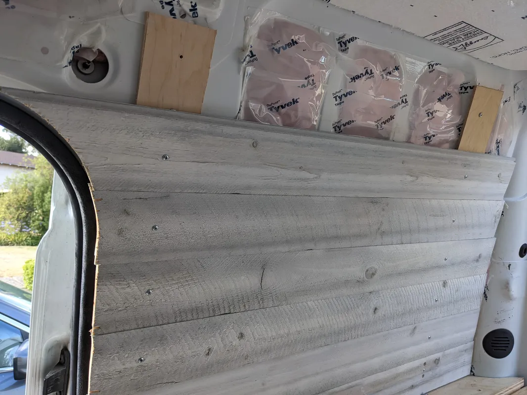
The cavities of the van’s chassis are filled with common pink batt fiberglass house insulation. To protect against moisture infiltration (which may collapse fiberglass or cause mold growth), all of the insulated cavities were sealed with Tyvek vapor barrier tape. Tyvek is commonly used on home construction for vapor mitigation such as this, and the tape is versatile enough for sticking to the van’s metal body. Additionally, the Tyvek barrier completely seals off the insulation from the interior cabin, preventing any potential skin or lung irritation while inside the van.
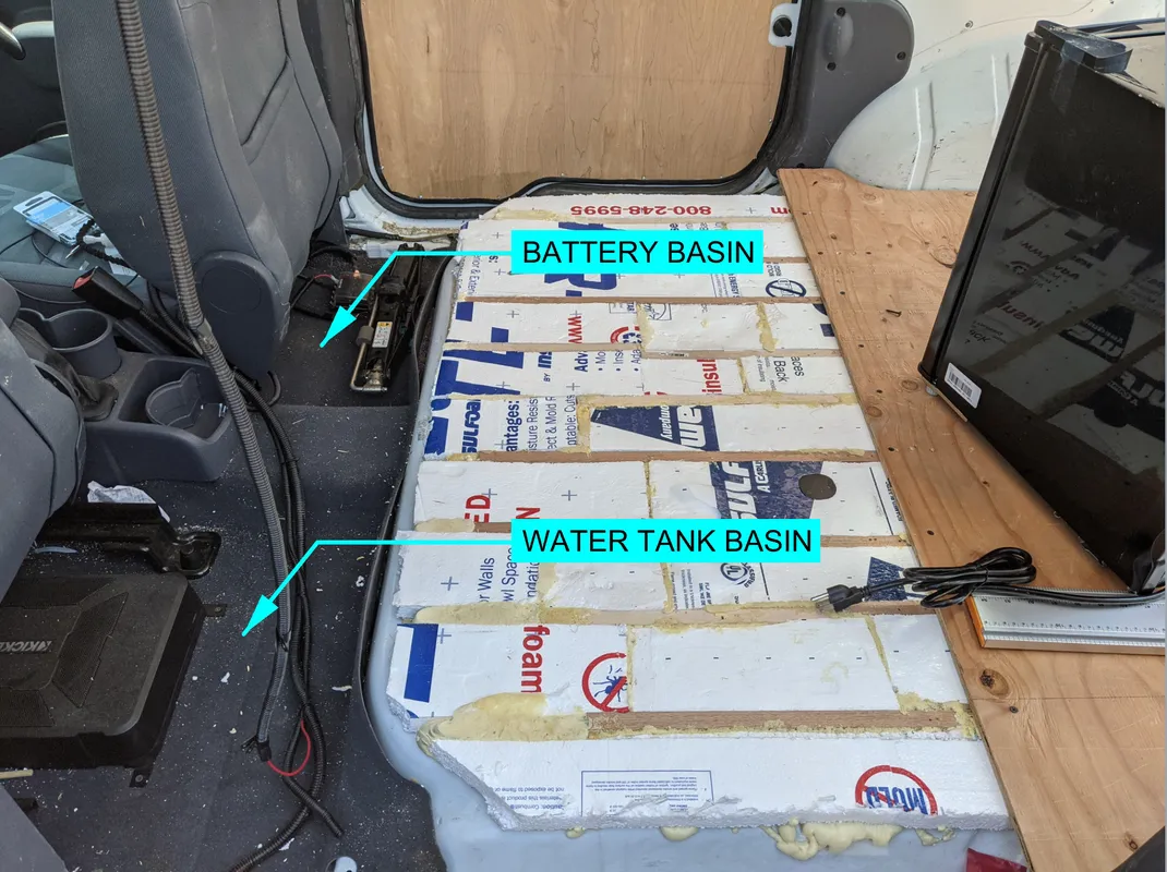
False Floor Removal
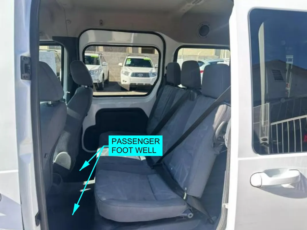
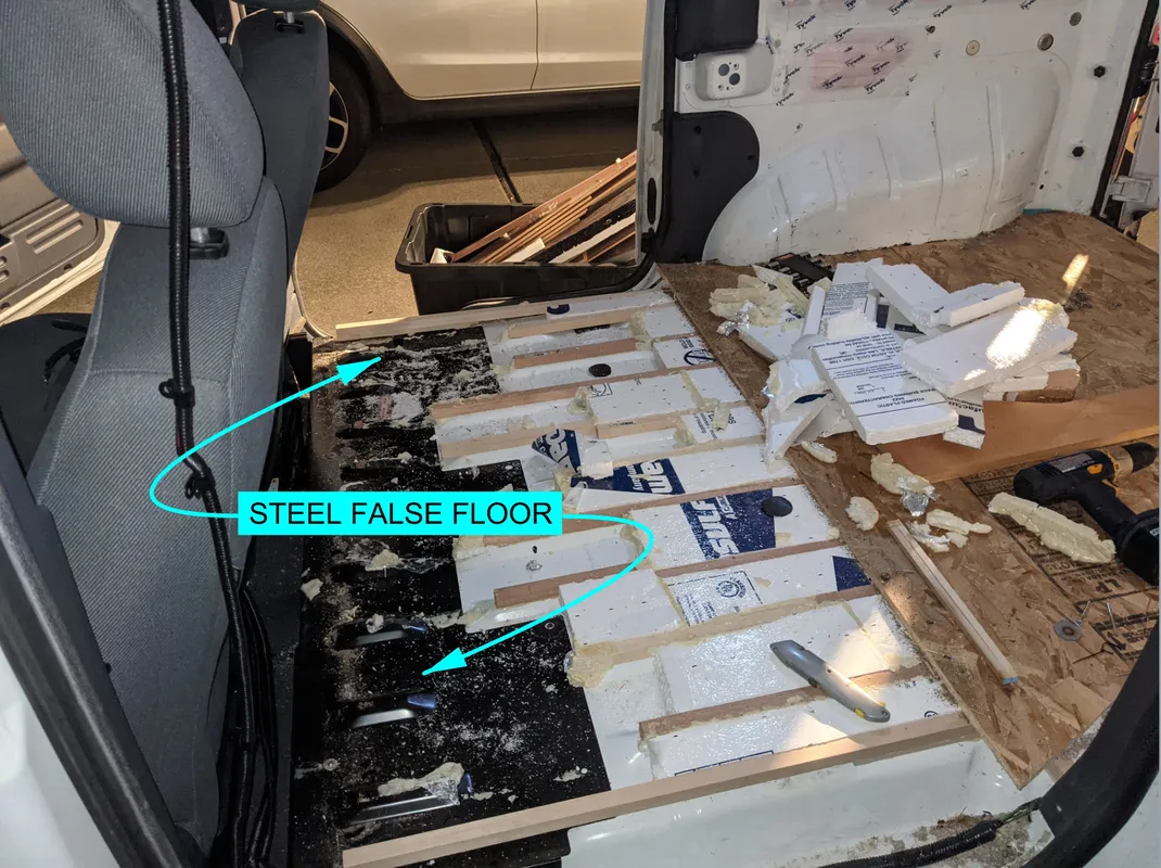
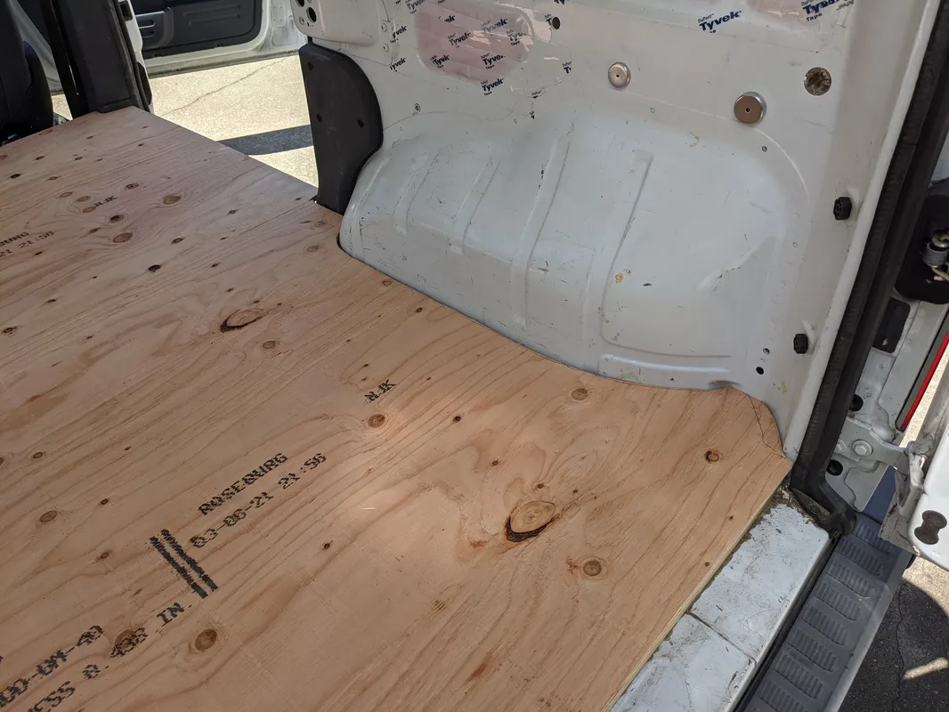
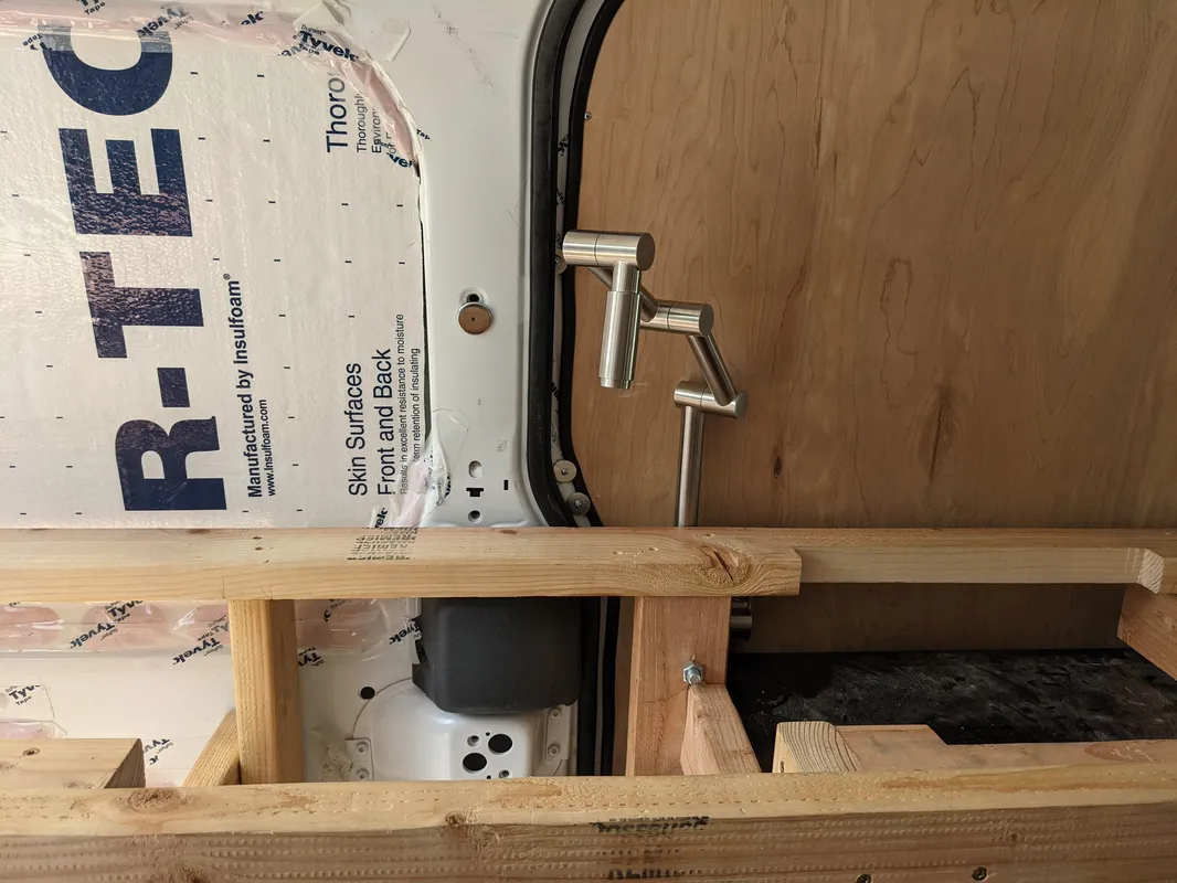
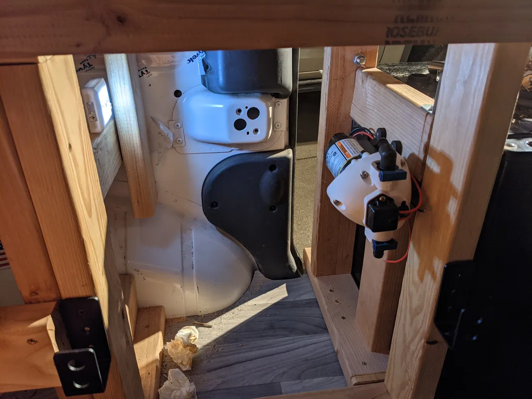
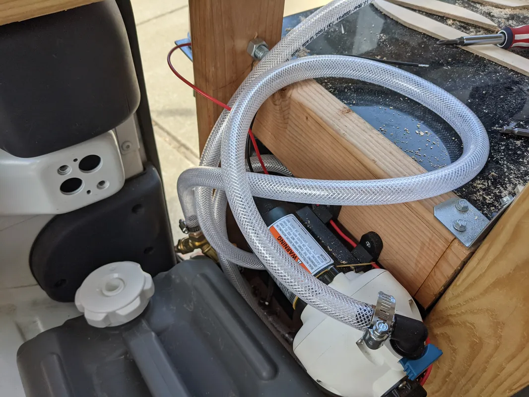
The 1st generation FTC was produced as both a passenger “mini van” in addition to the cargo van model. The cargo van model comes with a steel false floor which is used to extend the floor of the cargo bay, and cover up the seating “foot well” which was needed for the rear seats of the passenger van. This false floor was permanently removed in this build, by cutting off the welded attachments. This opened up some valuable space behind the seats, where the fresh water tank and house battery were “sunk” below the rest of the furniture.
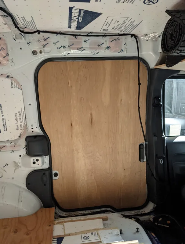
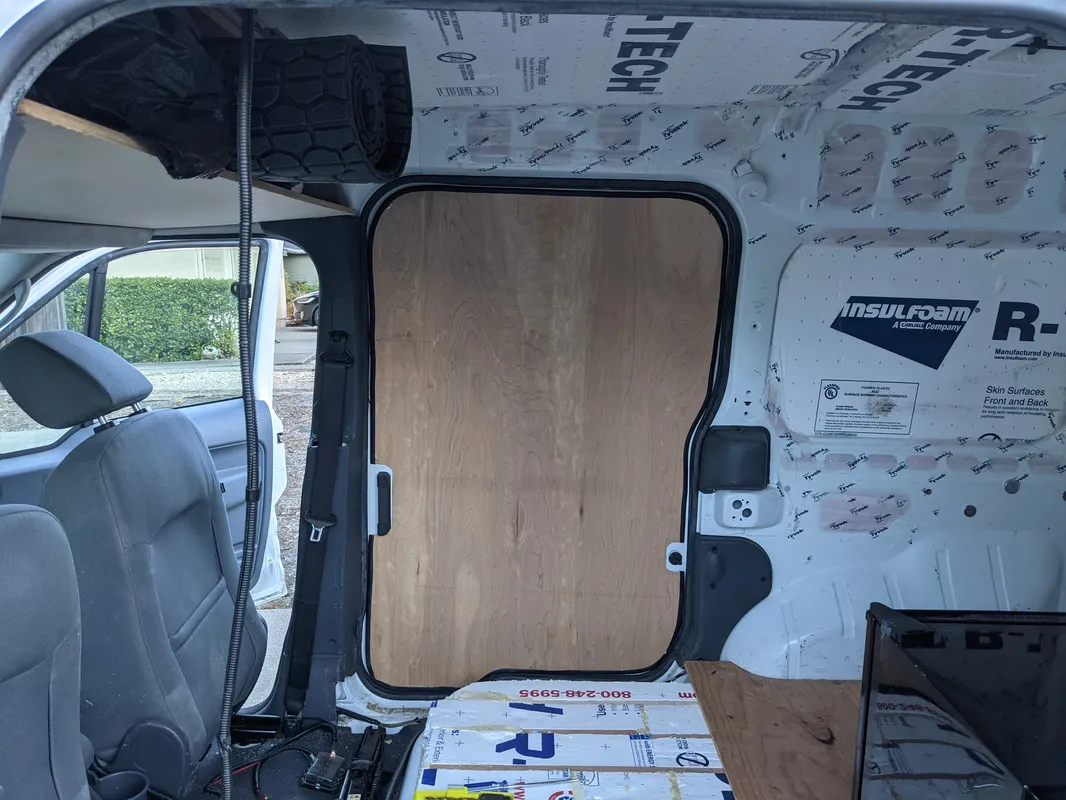
Door Paneling
The interior of the cabin doors are finished with a large plywood panel. The edges of the panel are wrapped with a rubber strip as a trim. The product used for the trim is typically used for car door edge protection and easily “snaps” on to the edge of the plywood.
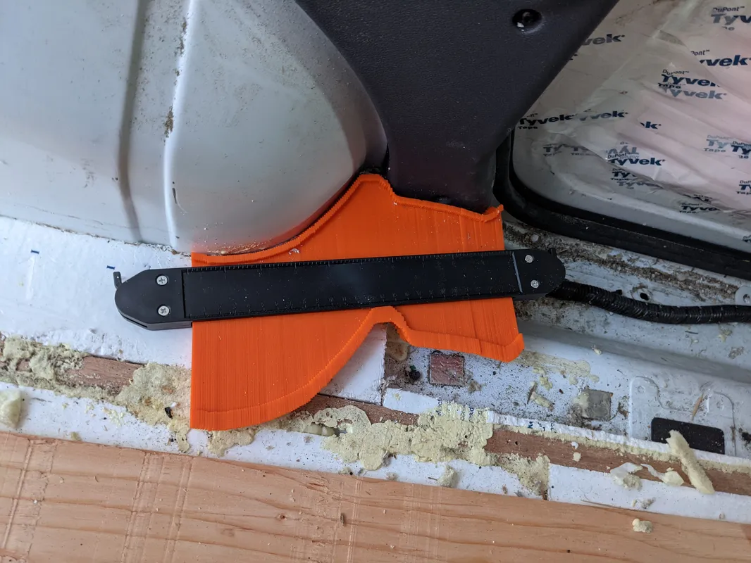
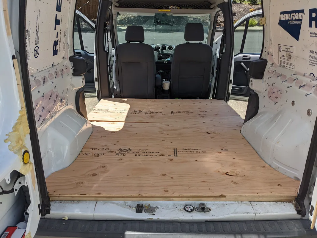
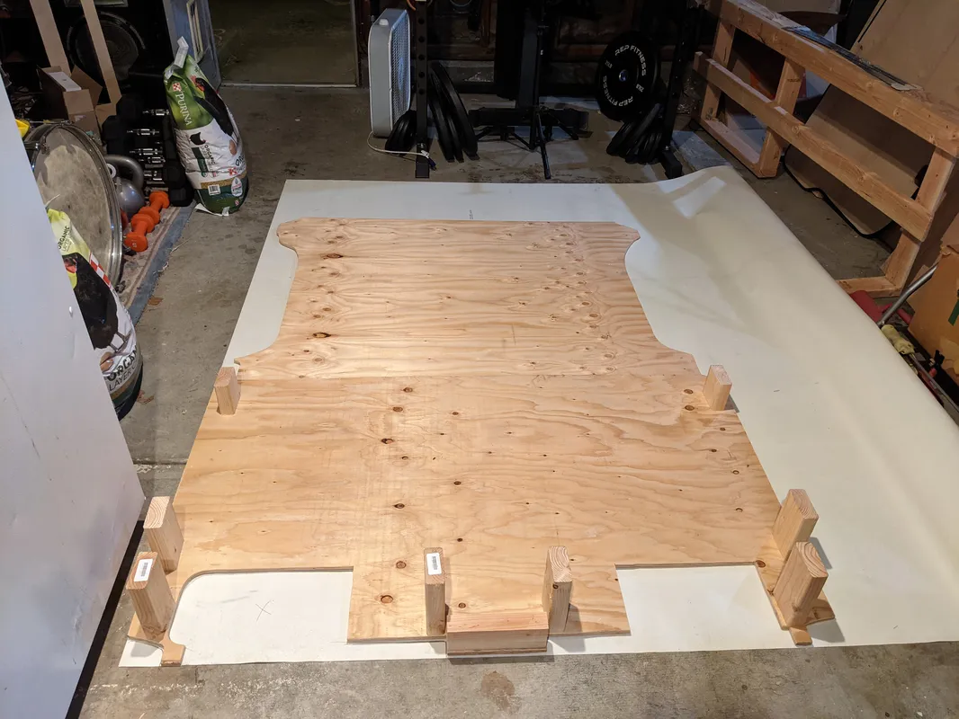
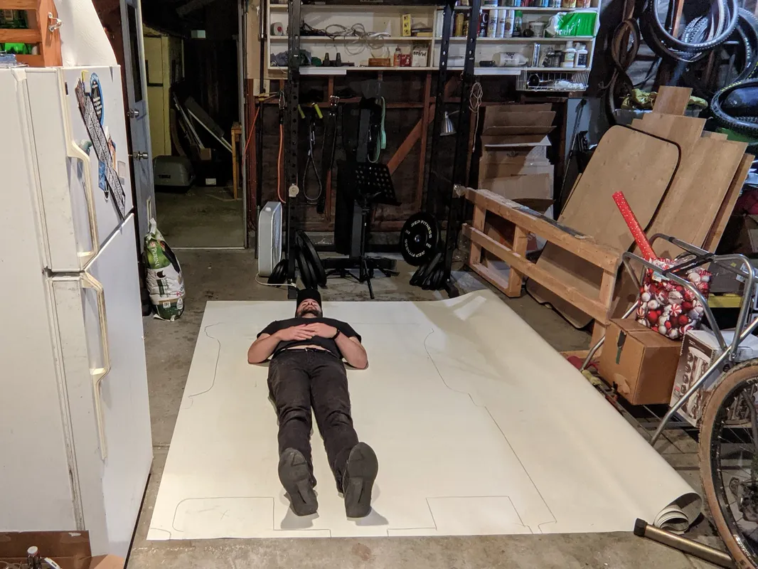
Flooring
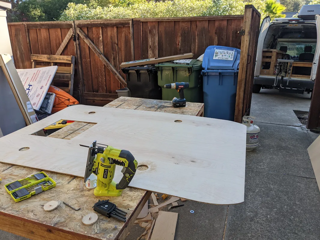
On top of the substructure is a continuous plywood flooring jigsawed to fit the exact contours of the van. The plywood is fastened down by drilling onto the substructure “beams.” The thick plywood then serves as a surface for the furniture and other elements to be securely drilled down wherever needed.
Roof Construction
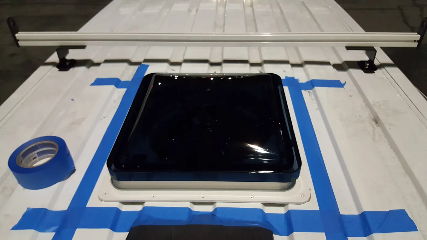
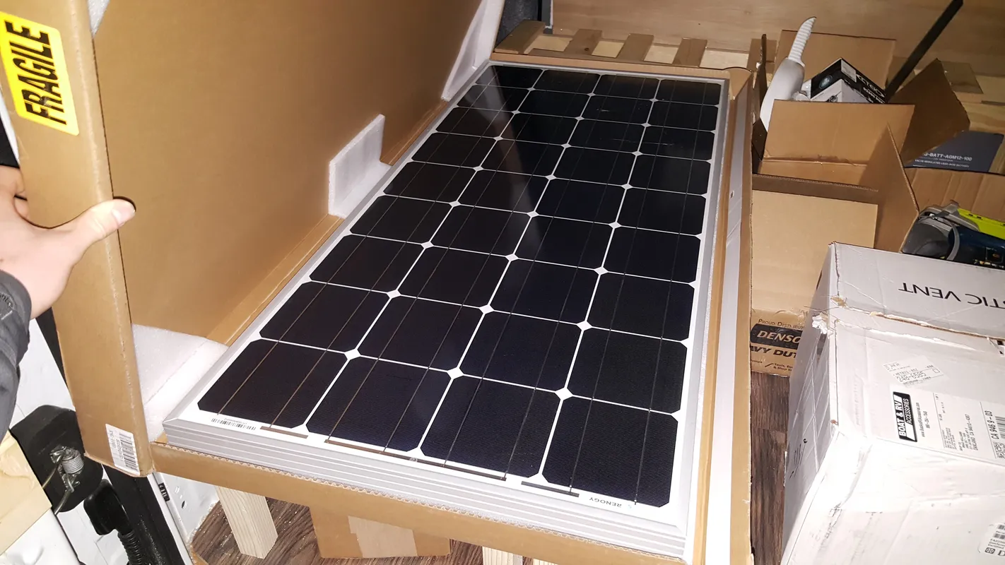
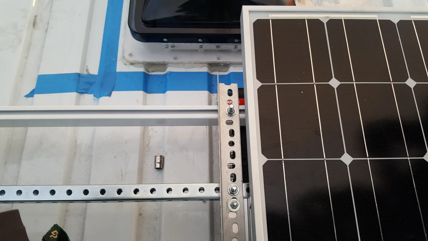
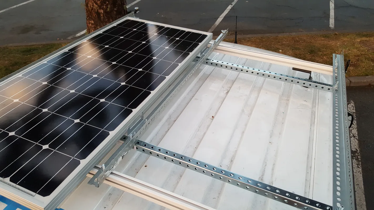
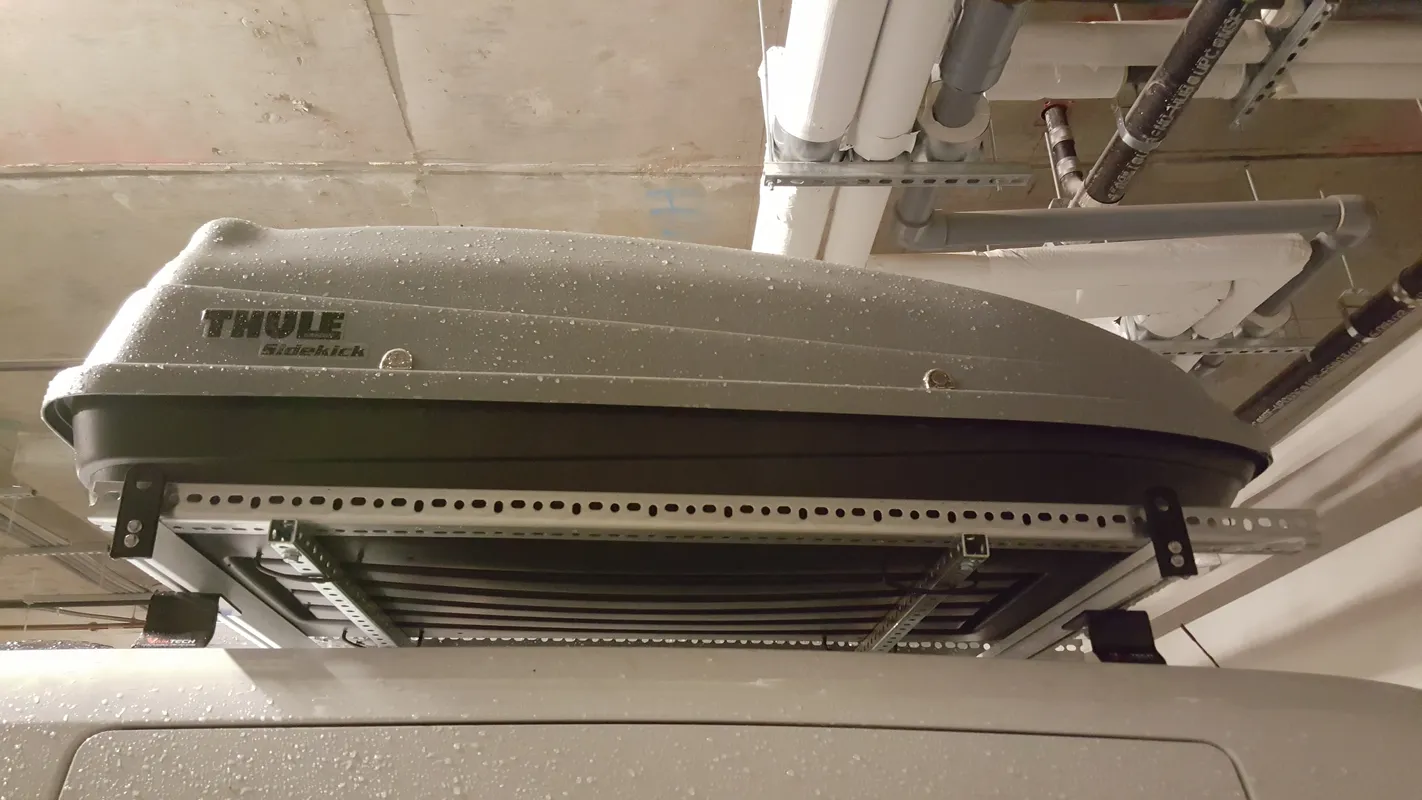
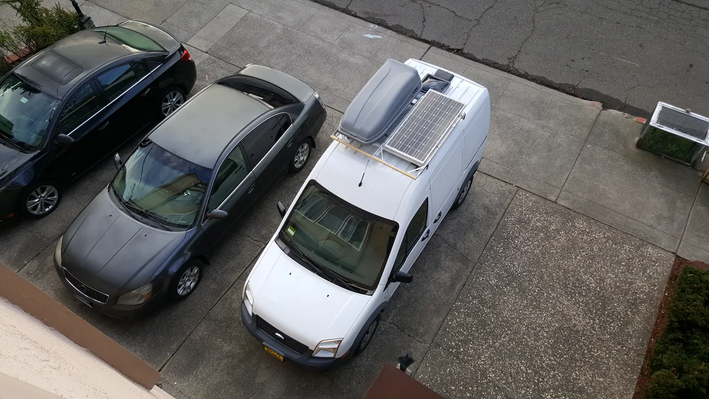
The van roof consists of three major elements: the roof fan, solar panel, and Thule storage box. The solar panel and Thule sit on a semi-custom roof rack. The FTC has fixed attachement points for roof racks, therefore the panel and Thule needed to be towards the front on these points, and the fan towards the back. This works out well because the fan will draw air in the back, from the cracked windows in the front, and create a nice cross ventilation across the length of the van.
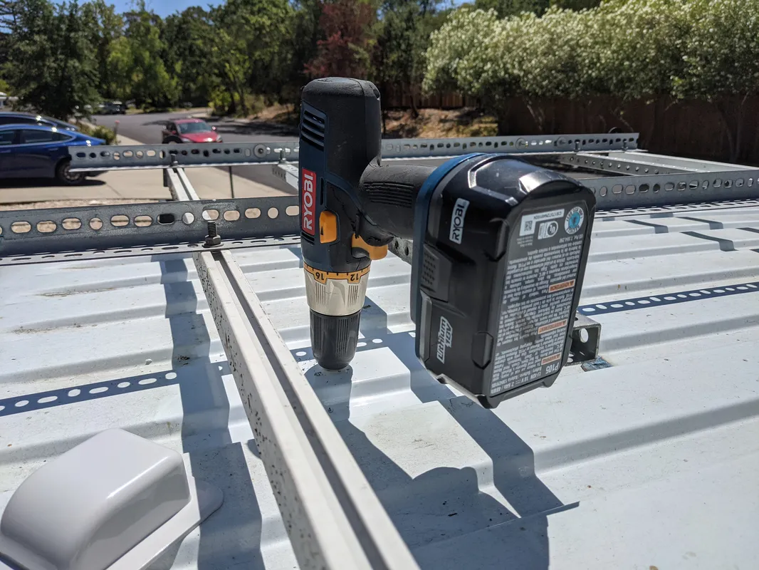
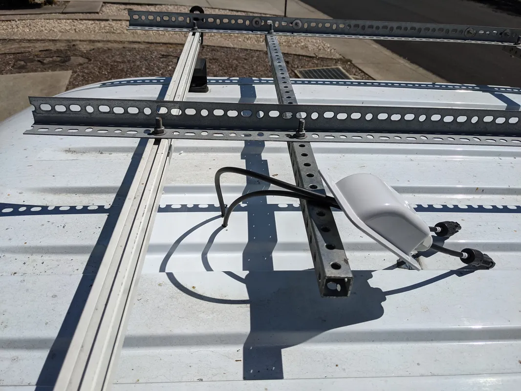
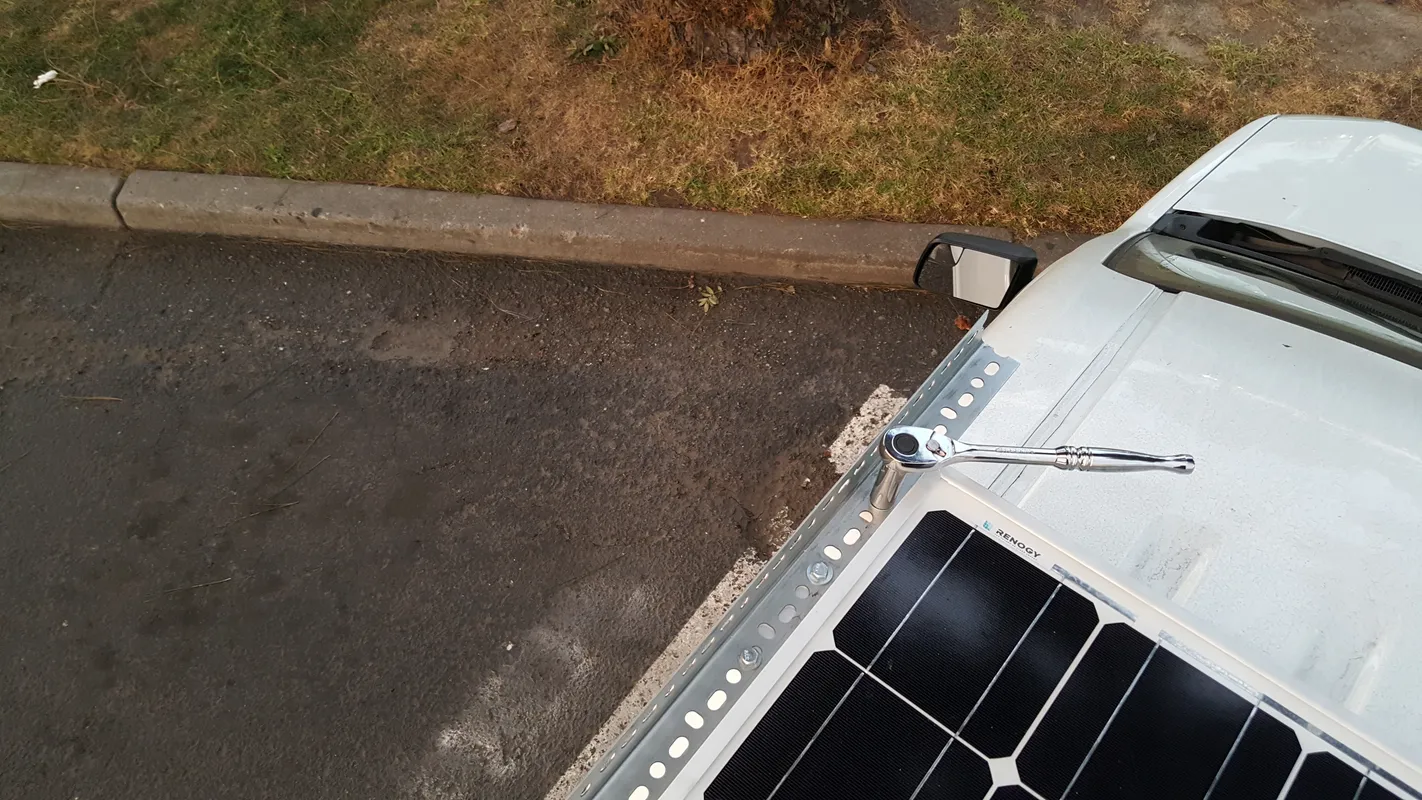
The main roof rack is a standard Van Tech rack with two bars spanning across the fixed attachment points. The challenge with the FTC was attaching the Thule and solar panel to a rack system with a fixed spacing. The solution was spanning a system of steel slotted angles and channels across the rack, to give the flexibility of different attachment points.
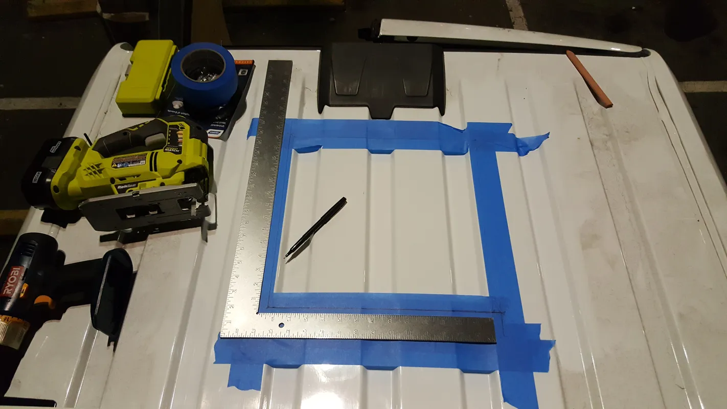
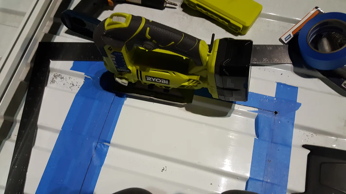
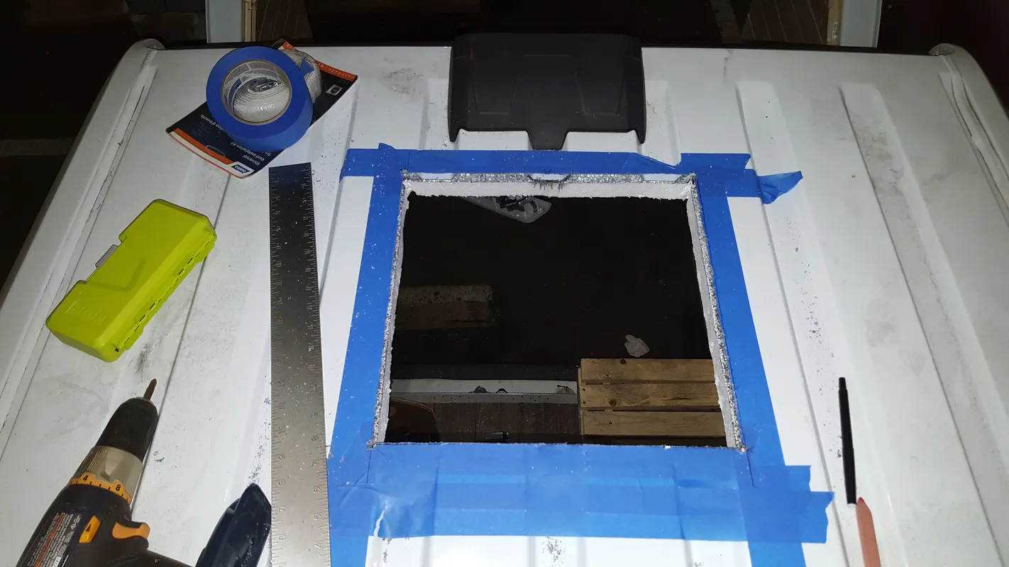
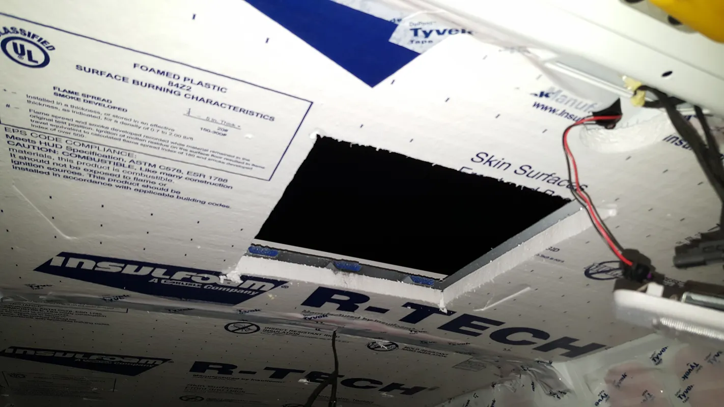
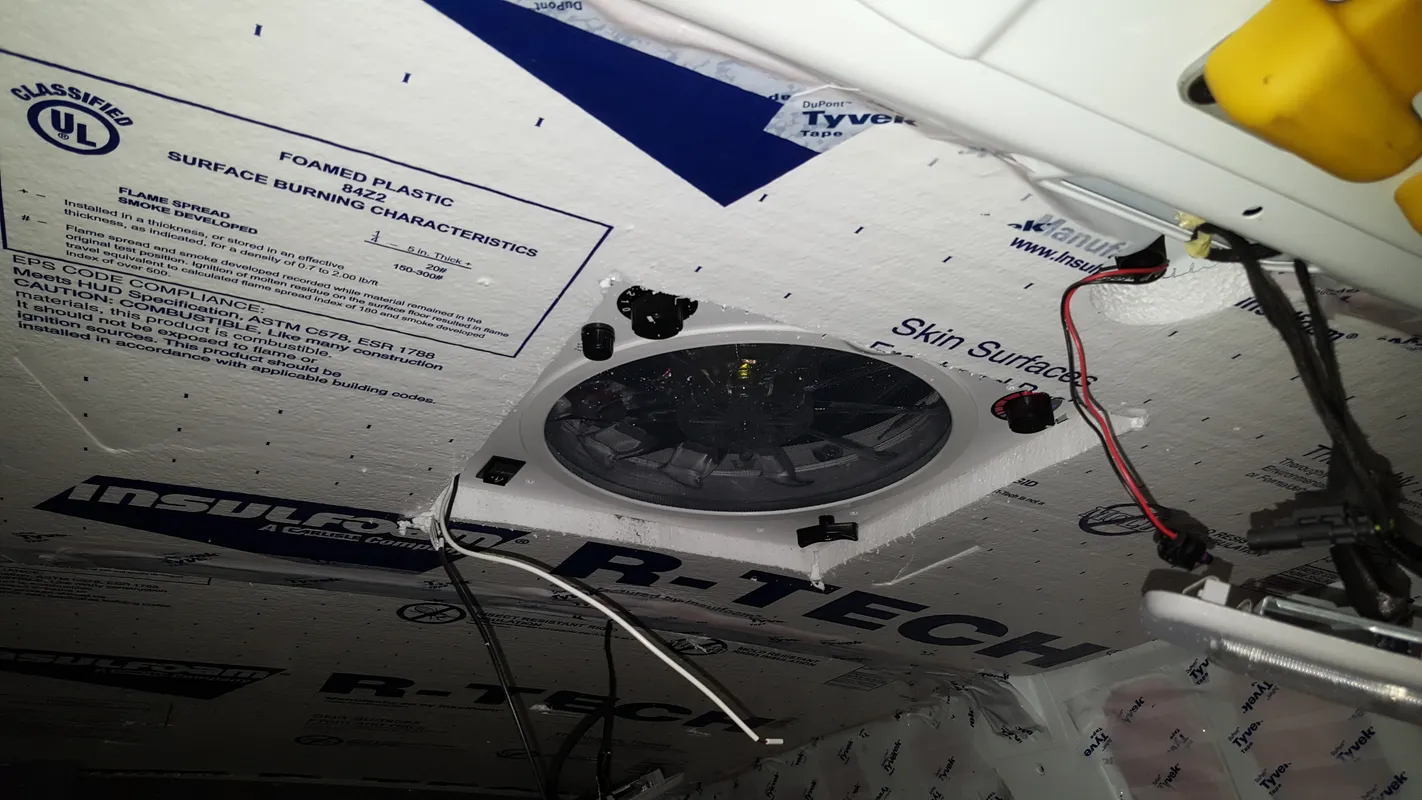
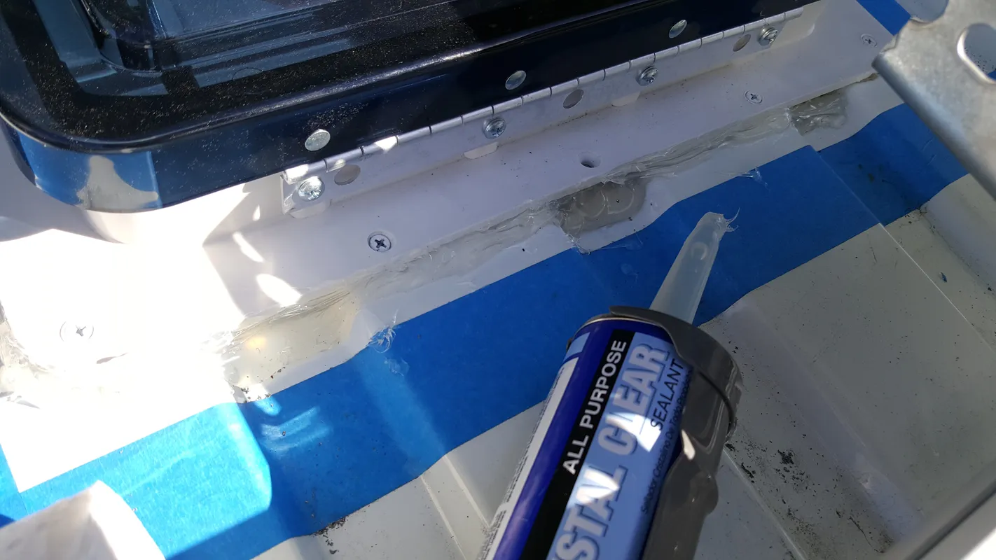
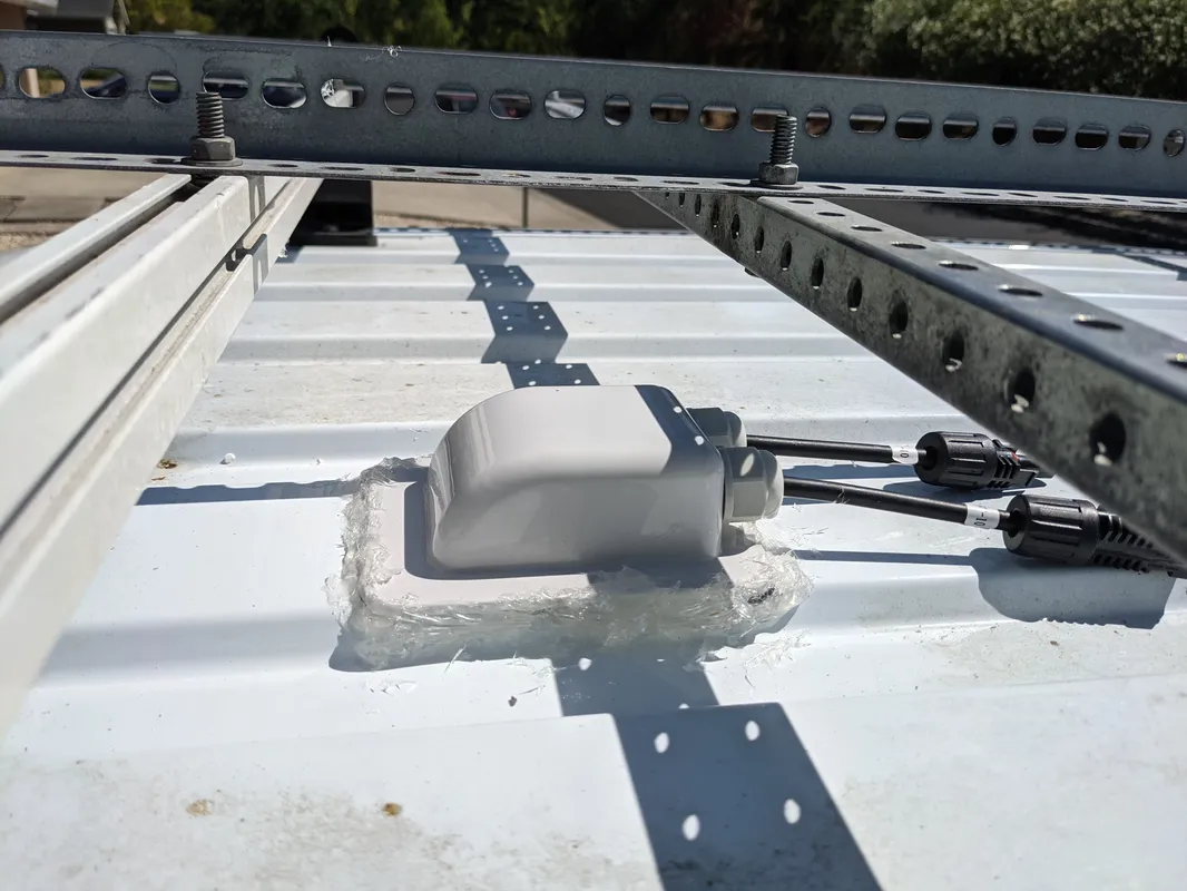
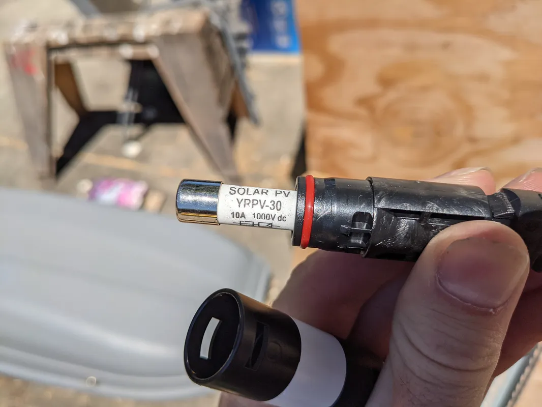
A large hole was cut out of the back of the roof to house the fan. The fan is drilled into the roof per installation specs, and is weatherproofed with roofing putty and roofing sealant caulking. Additionally, two small holes were drilled towards the front of the roof for the positive and negative solar panel cables. The holes are protected by a waterproof solar cable gland, with is adhered down with 3M strips and further weatherproofed with roofing sealant caulking.
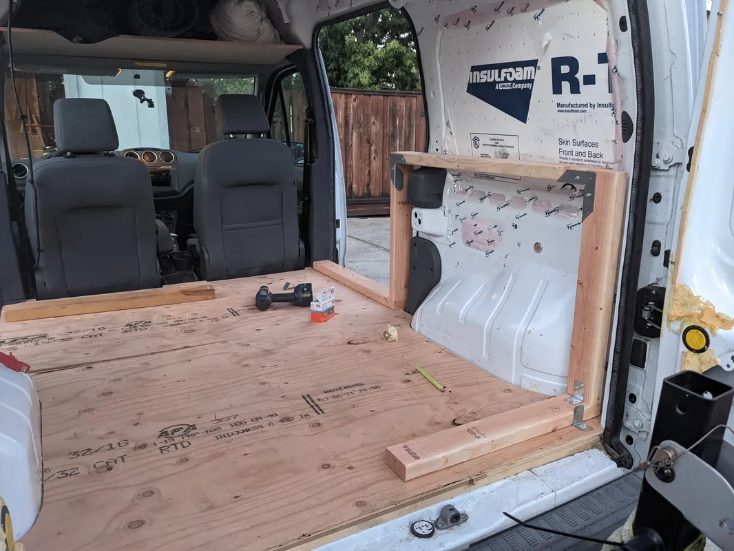
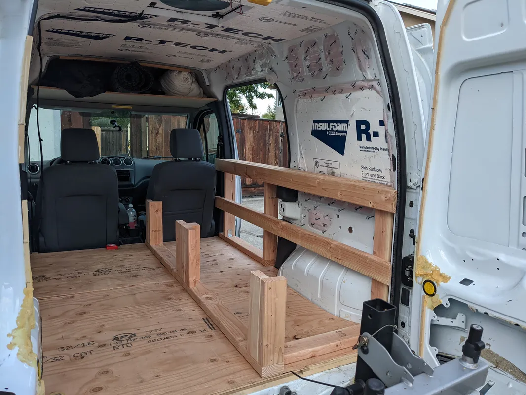
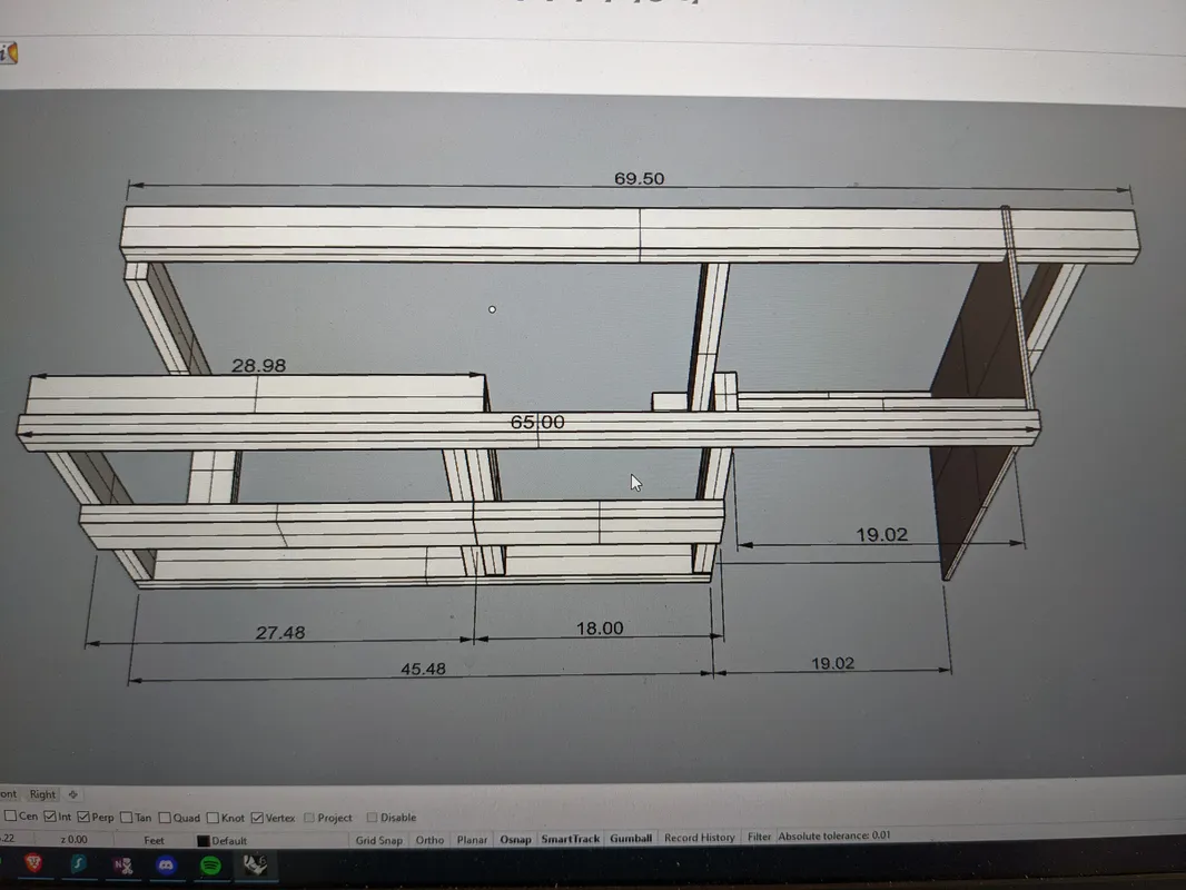
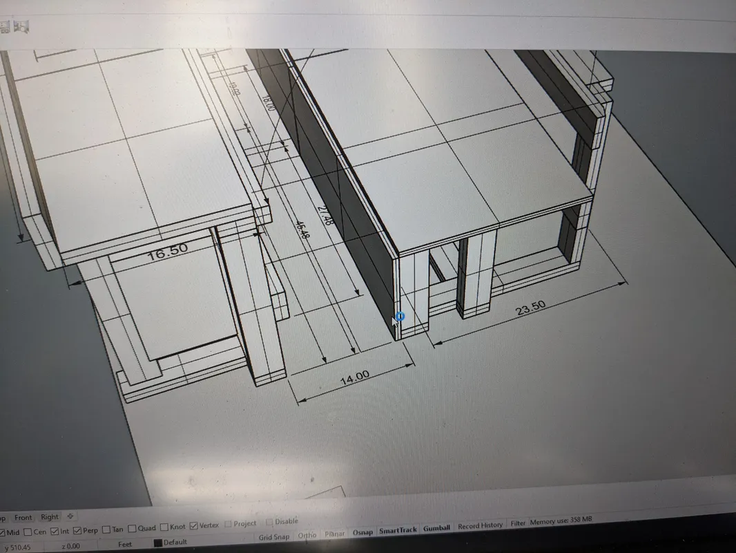
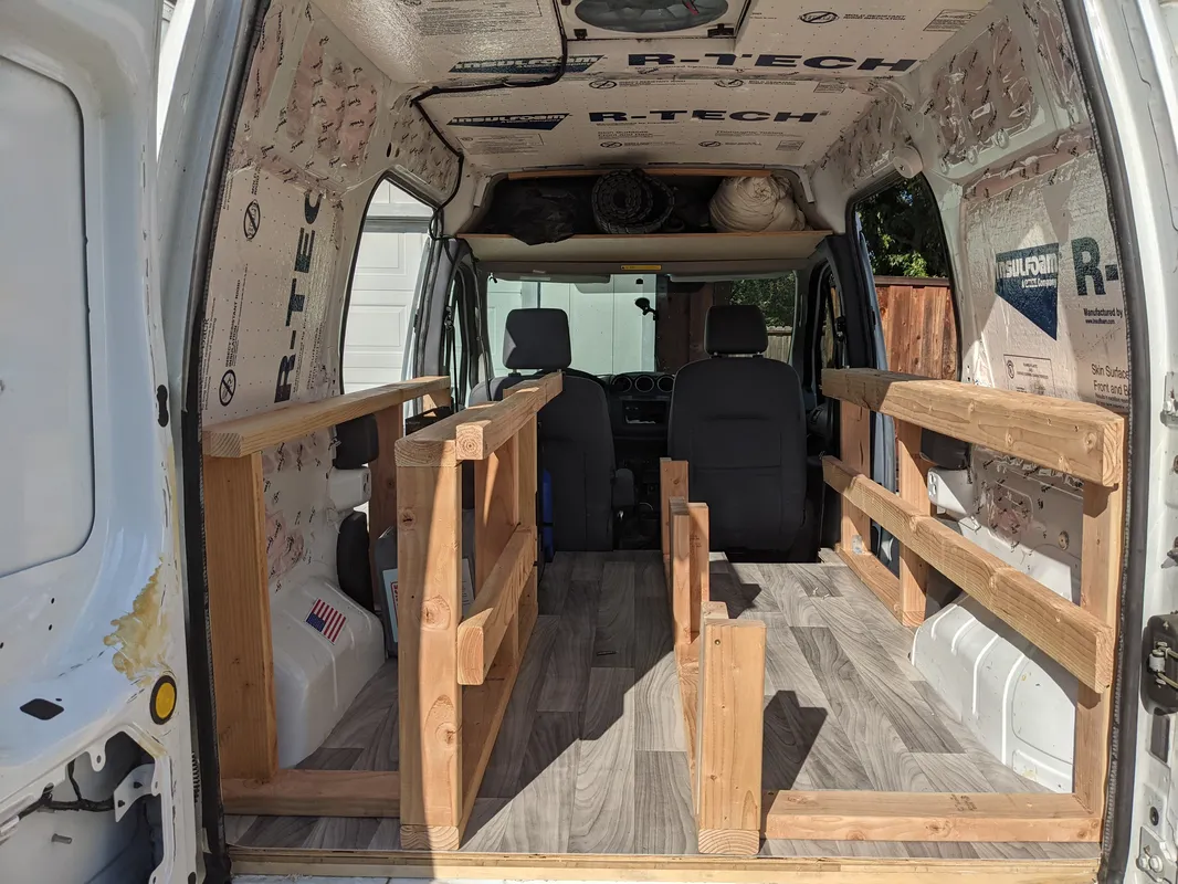
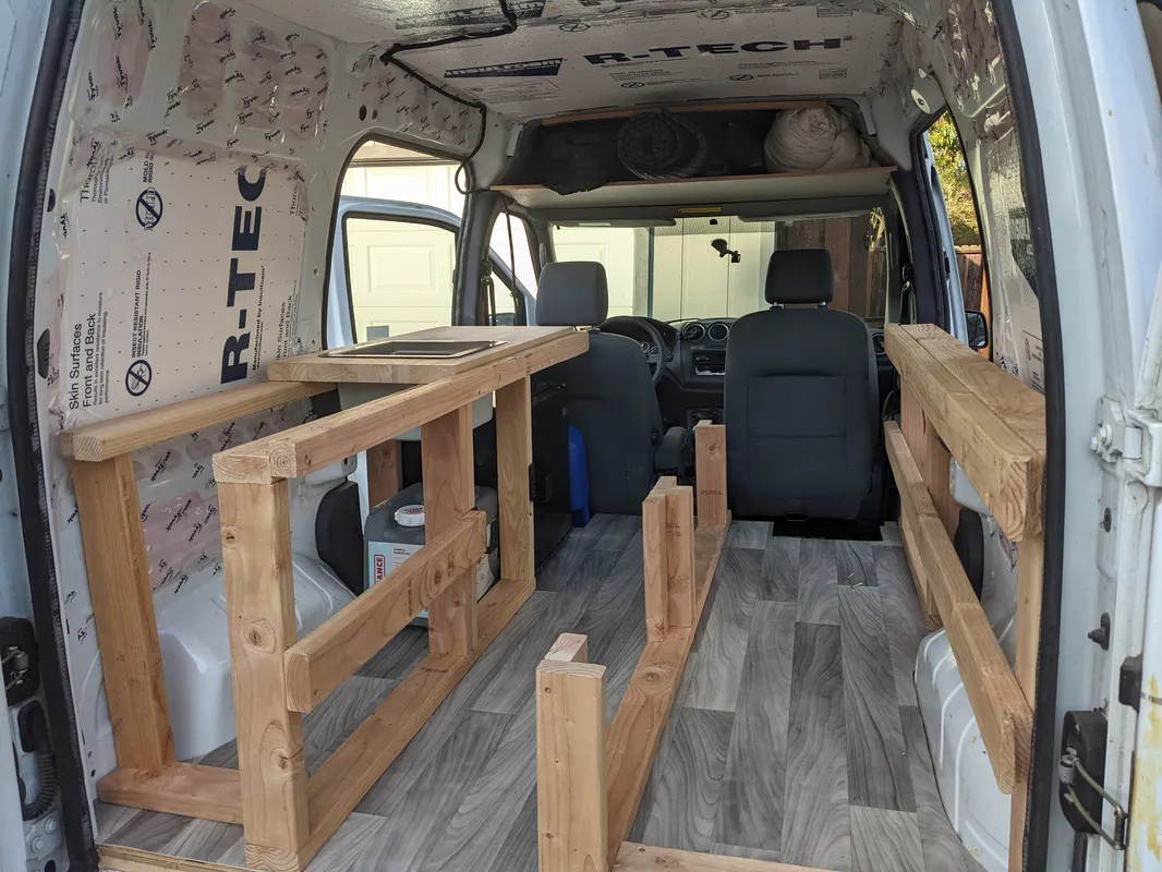
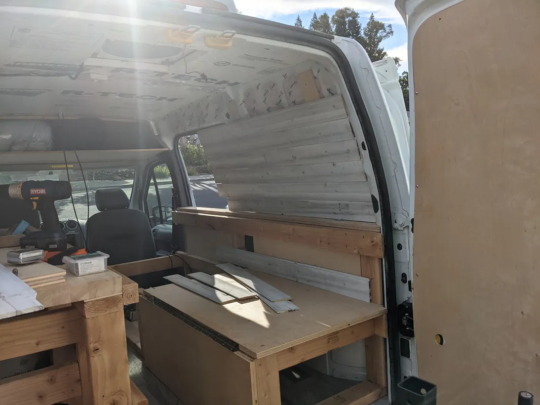
Interior Framing
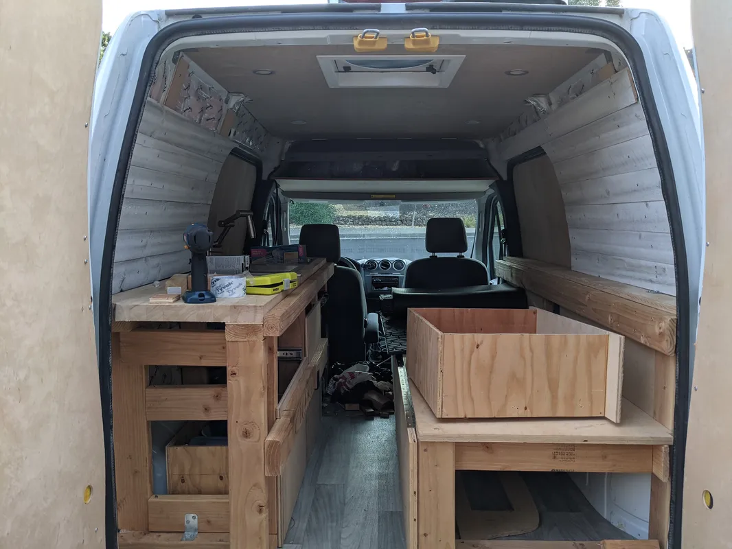
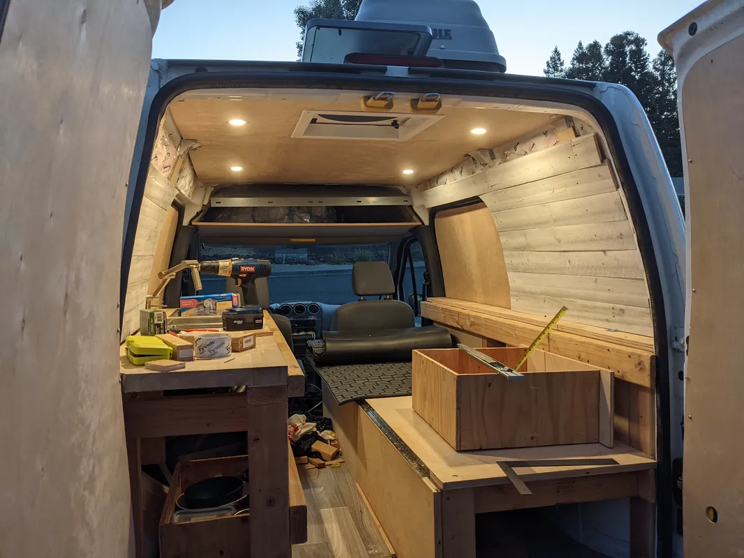
The furniture is largely built with standard 2x4’s fastened to each other with strong-tie connectors and structural screws. The framing was designed in a digital model down to the 1/4”, ensuring the tolerances for things like the modular squares, and kitchen appliances were accounted for.
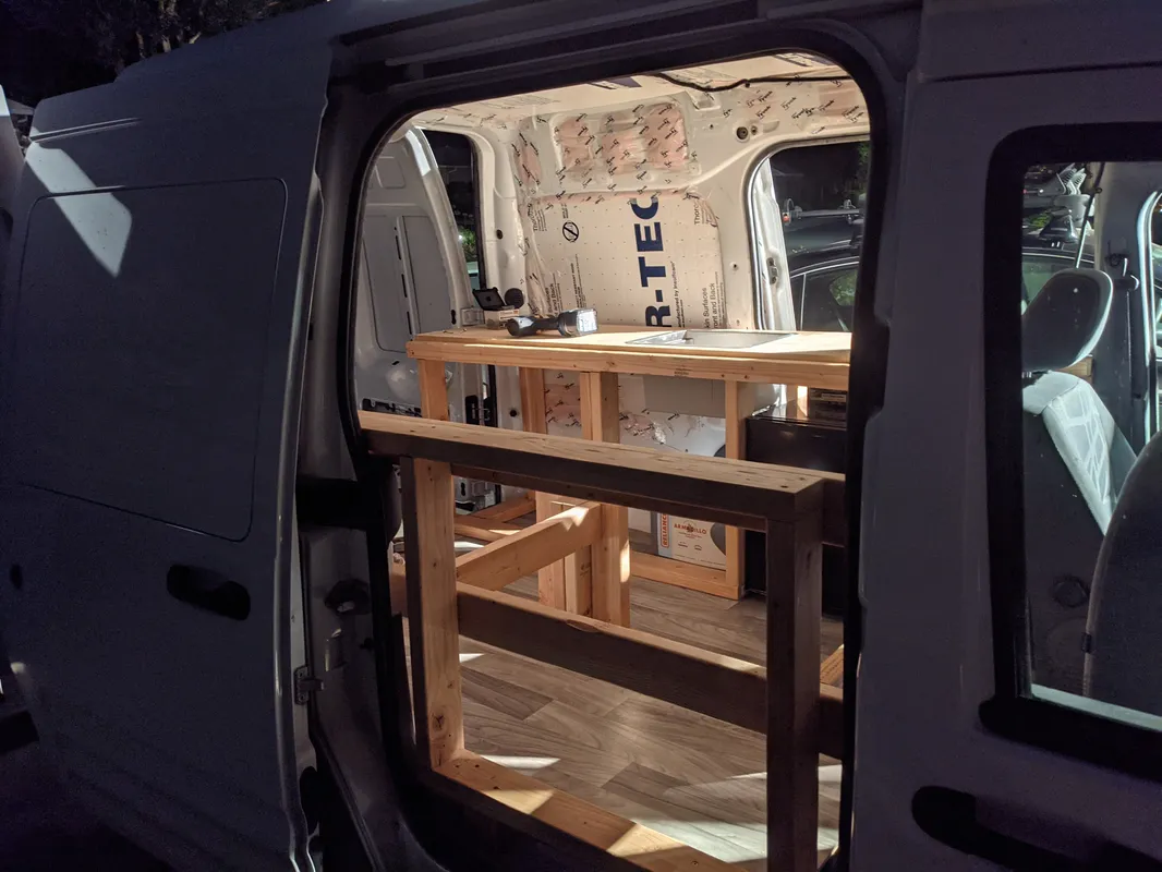
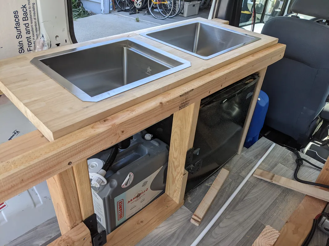
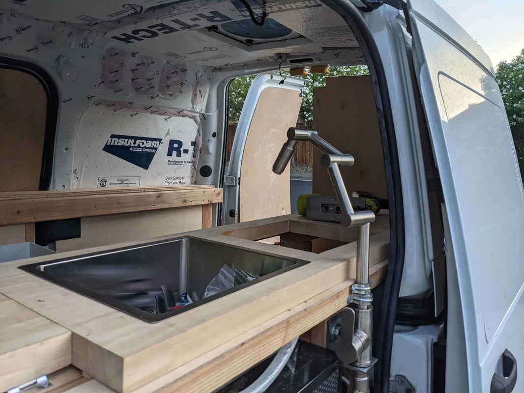
Kitchen Build
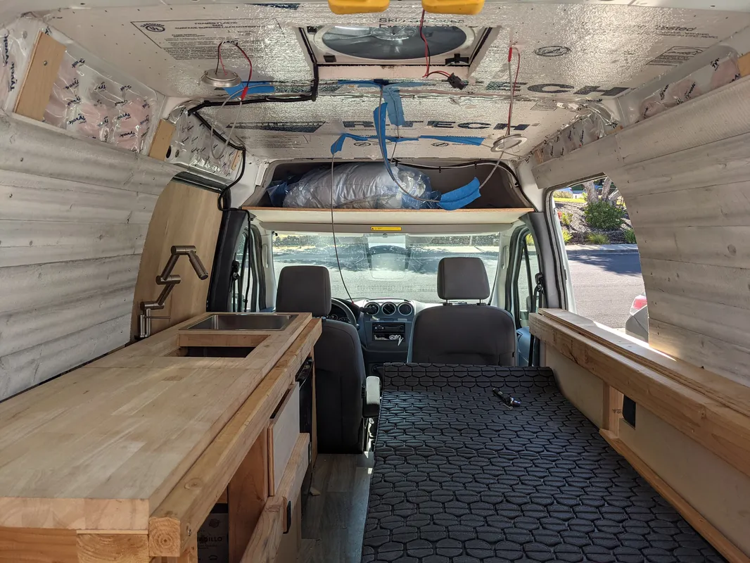
The kitchen has a large butcher block counter top installed, to simultaneously serve as a food-safe surface for cooking, and as a sturdy platform extension for the “Queen Camping” configuration. The drawers and cabinetry are made of plywood. On the side of the kitchen facing the bench, are 2x4 ledges running the length of the cabin, structurally fastened to the framing, for the sleeping platforms to sit on.
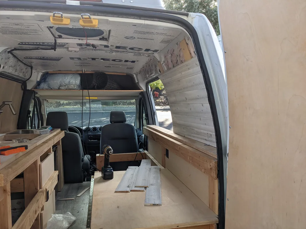
Interior Paneling
On top of the interior van surface, there are a series of thin wood battens which serve as the blocking for interior paneling. The ship-lap siding is screwed into these battens and custom cut to fit the contours of the van. The ceiling is a thin sheet of plywood attached to the van with strong-tie connections.
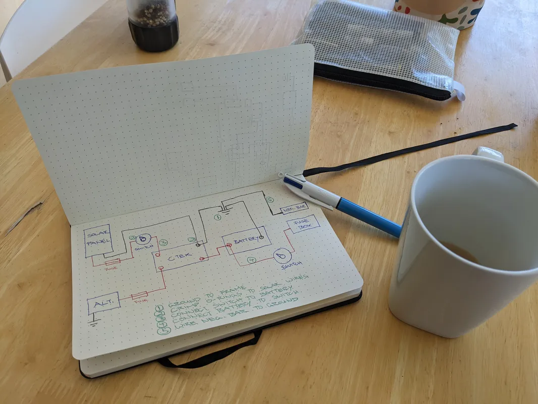
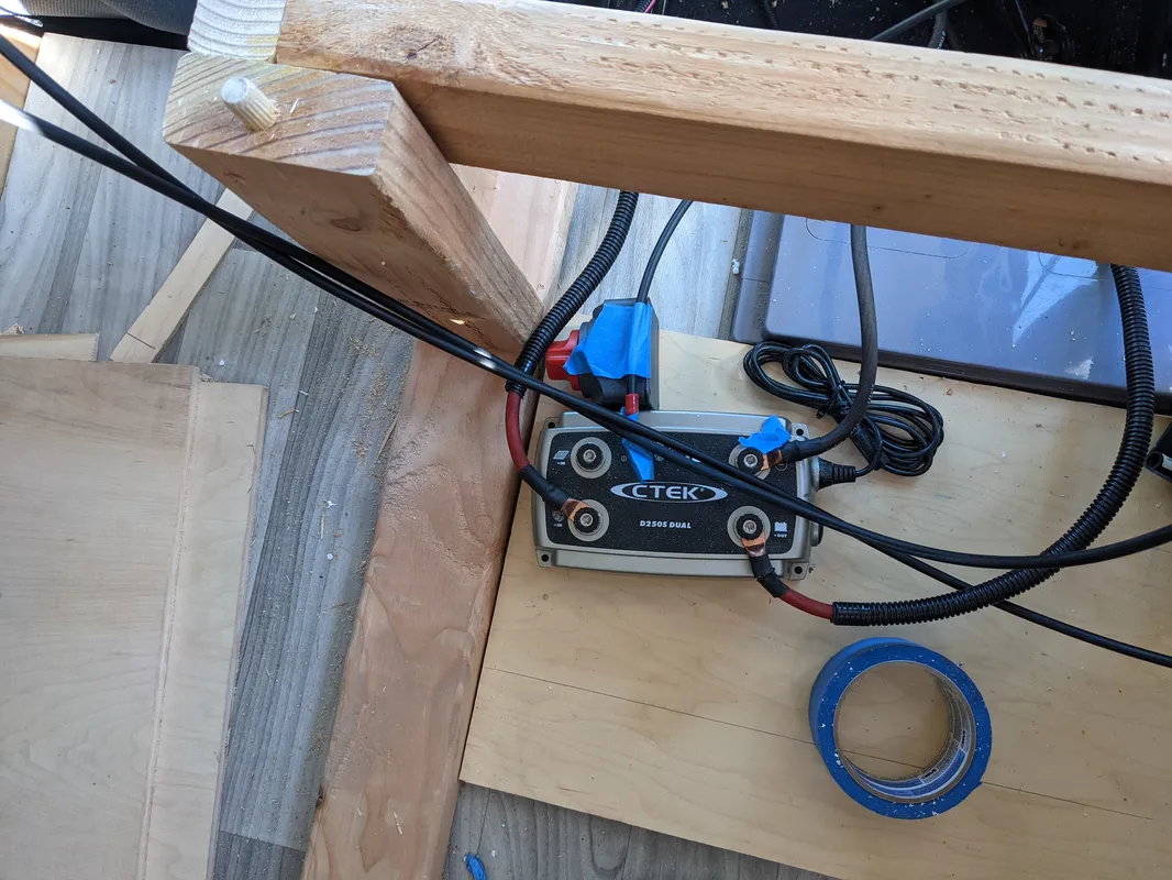
Electrical Wiring
Prior to the final ceiling installation, the solar wiring from the roof and recessed puck lights were configured, which were later recessed and concealed within the ceiling.
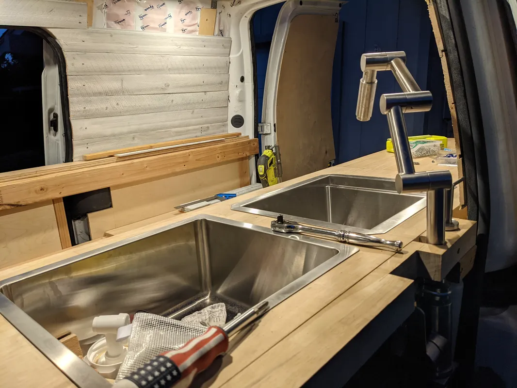
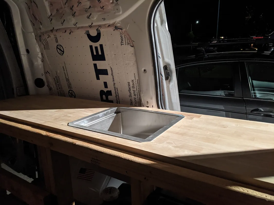
Kitchen Carpentry
The plywood drawers are built with plywood and installed with slow-close sliders in the largest part of the kitchen framing. As a finishing touch, the butcher block counter top was extended with a custom fitting for the sink and soap dispenser, to take advantage of every 1/4” against the sliding door